Viewer Windowing and Shaders
Back to Contents
First, make sure you have:
- A working build of the viewer
- A text editor you like, preferably with syntax highlighting for JavaScript and PHP (The one used in the example)
(as of June 2020)
Common Shader Control
- Logging
viewerResetShaderLog(): Clear the shader log but not the shaders themselves. Shaders can be removed withviewerRemoveShader(name)viewerGetShaderLog( separater1, separater2 ): Get a string containing all of the shader changes for the entire viewer (shaders are not constrained to a particular image). The components of every shader change are separated byseparater1, and every shader change is separated byseparater2.- Every shader change will start with a flag indicating the change type
- There are 6 main shader change types
i: Invoke - this message will have 2 extra components, the name of the shader invoked (might beoff, if shaders are turned off), and the time that shader was invoked.r: Remove - this message will have 2 extra components, the name of the shader removed, and the time that it was removed.m: Message - this message will have 2 extra components, the message itself, and the time it was logged.g: Gray Window Creation - this message will have 4 extra components, the name of the newly created shader, the level, width, and time it was created.v: Value Window Creation - this message will have 4 extra components, the name of the newly created shader, the level, width, and time it was created.c: Custom Shader Creation - this message will have 4 extra components, the name of the newly created shader, the vertex shader, fragment shader, and time it was created.
-
There are other advanced shader change types (which almost no one will enounter)
G: Full 12 bit (scaled to 8 bit) gray window shader creationV: Full 12 bit (scaled to 8 bit) value window shader creationh: High 16 bit (unscaled) gray window shader creation
- Logging Tips:
- Creation of custom shaders log the entire shader code, it is recommended to not log these events, and log a message stating the shader's creation instead. This will require less data to be passed back to the server and make your logs cleaner.
- Custom shaders are made of code with contain commas, semi-colons, and new lines. Because these would be common choices for separators, you will have
to become more creative. Remember that separators can be many characters long:
viewerGetShaderLog('2222222','5555555555')is perfectly legal. Not the most legable, but if you're autoparsing and need to return custom shaders in your log, you probably already gave up on legablity.
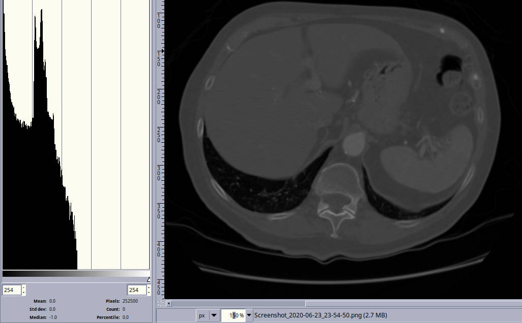
This image had a window width encompassing the full 12 bit dicom,
notice how the upper values are mostly unused.
- Shader Creation
- Notes:
- The following functions all have the optional parameter
log, if this is false, the change will not be logged, otherwise shader changes are logged by default. - If you create an image windowed from -1000HU to 1000HU as recommended, any window with a high value over 1000 will not be
accurate
because values > 1000 are now = 1000. Normally this missing data will go unnoticed, but you should be aware of this. - If a shader is added with the same
nameas a previous shader, the previous shader is overwritten. If that shader was currently active, the new shader will become active.
- The following functions all have the optional parameter
- Custom Shader Creation:
- Custom shaders are written in the WebGL varient of glsl an example can be made at the bottom of the page.
- When referring to the pixel components in glsl, the values range from 0 to 1, not 0 to 255
- Function:
viewerAddCustomShader( name, vertexShader, fragmentShader, optional log ): Add a shader namednamewith the shader components defined as strings. You can set thevertexShadertod
if you want to use a simple default vertex shader. However you always have to specify thefragmentShader. 1
- 8 bit
Zeroed
Window Shader Creation (Recommended for CT images):- It is strongly recommended that, for windowing purposes, you use only these
zeroed
shaders. - These shaders expect source images rendered at 8 bits per color with level at 0HU and width at 2000HU
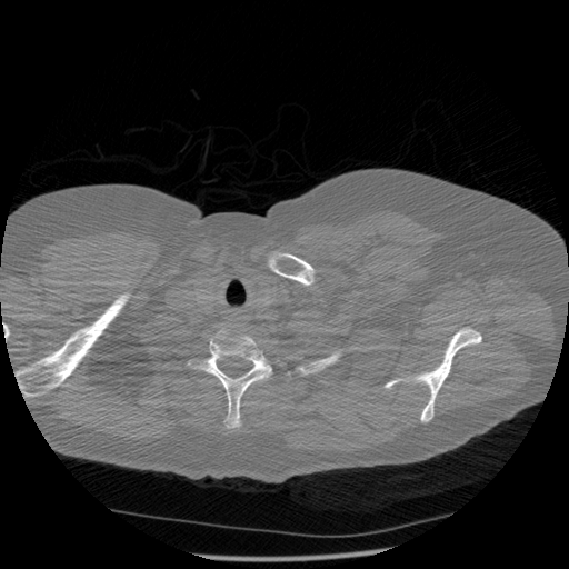
- As seen in the image above, humans are quite squishy, even Vin Diesel. Almost all values in our bodies are in the lower half of what is available in a typical dicom image (less than 1048HU).
- If you don't know your bits per color, but are outputing dicoms to png or jpg, it's safe to assume they are 8 bit.
- Functions:
viewerAddWindowingShaderGray( name, level, width, optional log ): Create a windowing shader namednamewith the specified windowlevelandwidth. This creates a grayscale shader which expects every pixel to have red = green = blue. If this is not the case, use value shading below (obviously you don't have to check every pixel, it won't break anything if this is off a little, CT images are grayscale).* 1viewerAddWindowingShaderValue( name, level, width, optional log ): Create a windowing shader namednamewith the specified windowlevelandwidth. This converts the pixel values to HSV, and only windows theValuecomponent. This is better for non grayscale images.* 1
- It is strongly recommended that, for windowing purposes, you use only these
- 8 bit Full Depth Window Width Shader Creation:
- These shaders expect source images rendered with level at 1048HU and width at 4096HU (full 12 bit range)
- Dicoms tend to store data in 12 or 16 bits. This shader works with that range, but reduces the depth to 8 bits (so data is lost, but these images still work like regular images).
- Normally human bodies don't need to show any variety above 1000HU so it is generally advised to prepare your source images to work with the zeroed shaders above.
- Because the usual contrast is roughly halved, the pixel values are expanded in these shaders to match the HU conversions for the zeroed shader.
- If you don't know your bits per color, but are outputing dicoms to png or jpg, it's safe to assume they are 8 bit.
- Functions:
viewerAddWindowingShaderGrayFull( name, level, width, optional log ): Create a windowing shader namednamewith the specified windowlevelandwidth. This creates a grayscale shader which expects every pixel to have red = green = blue. If this is not the case, use value shading below (obviously you don't have to check every pixel, it won't break anything if this is off a little, CT images are grayscale).* 1viewerAddWindowingShaderValueFull( name, level, width, optional log ): Create a windowing shader namednamewith the specified windowlevelandwidth. This converts the pixel values to HSV, and only windows theValuecomponent this is better for non grayscale images.* 1
- 16 bit Full Depth Color Window Shader Creation:
- Never use this shader unless you know exactly why you need it
I am only including it as a means to test contrast correctness for different windowing levels. If your trials need higher color depth, either use several files with their own prerendered window, or use a CPU based viewer (not this one). If you don't know whether or not you need higher color depth, you don't. - This shader expects images rendered as pngs with the highest 8 bits stored in the red component, and the lowest 8 bits stored in the green.
- This shader combines 8 bits from the red and green components at runtime to show a 16 bit grayscale image.
- Because this contrast is 16 times higher, the pixel values are reduced in this shader to match the HU conversions of the 8 bit shaders
- No stand alone program will do these fairly specific conversions, you will have to rely on custom solutions (my asc2png16.py script creates these images from ascii files).
- Function:
- Never use this shader unless you know exactly why you need it
- Notes:
- Shader Control:
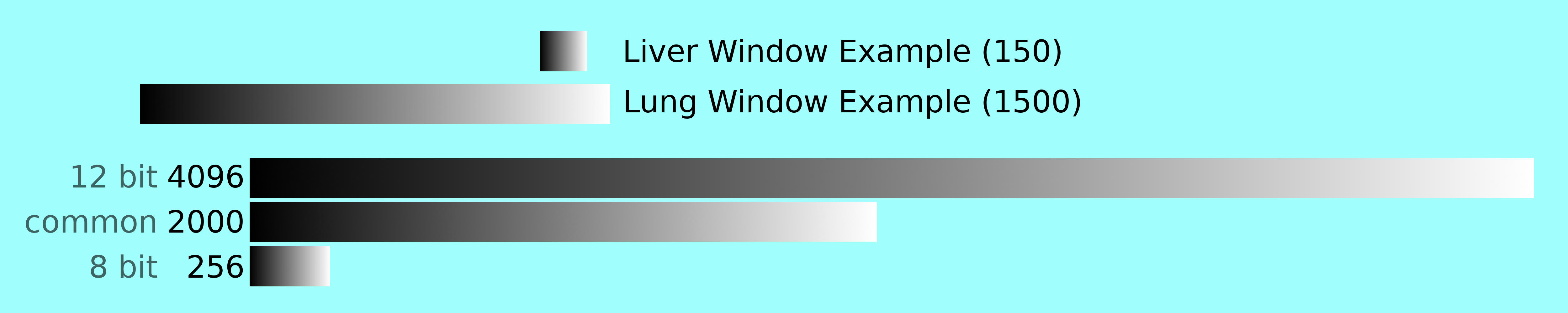
*Windowing levels and widths are specified in decimal values which linearly progress from 0 (black) to 1 (white). However you will likely encounter
Hounsfield Units (HU). These specify density, not color. Our bodies typically range from -1000 HU (air) to
1000-ish HU (bone).
Conversion:
Conversion:
| • | level | = (1,000 + HU level) / 2000 | HU = | 0.5 viewer unit(s) | |
| • | width | = HU width / 2000 | HU = | 0 viewer unit(s) |
- Radiology Cafe has good images illustrating this (a third of the way down the page). Just remember that even though their images show the range topping off at 1000, HUs do technically go higher than this.
- Some values will be above 1 and below 0. This is not an error (and is desired, it just means portions of the spectrum are discarded)
- HUs do go above 1000, Dicoms tend to retain this extra range, but most windows discard it. These high values are very dense, yet we are quite squishy.
- Grainyness is common, but as the window width decreases, color difference increases, and the JPEG's compression defects will show.
1 Returns true if the operation was successful, false if failed.
Advanced Windowing
For easy transmission of images over the Internet as well as a uniformly smooth runtime experience, this viewer requires images which have 8 bits per color. Dicoms, on the other hand, often store 12 bits per color allowing them to show a much greater change in contrast. Because these images are grayscale, where all colors are equal, we can store half of the bits in one color, and half in another. The supplied way of doing this for the viewer is to store the top half of the bits as red, and the bottom half as green (blue is unused).Unfortunately, this means the images will have to be stored losslessly (as a png), and will be harder to compress generally (about twice the size of a normal, grayscale, png). Because of this, it is recommended that high bit depths are only used for internal testing, and never in practice.
If you do need a higher bit depth, it is recommended that you use a viewer designed for that, spread your
windowsacross multiple images, or possibly make your own glsl shader which works better with jpeg's compression.
The 8 bit windowing shaders which come with the viewer expect the source image to be rendered with a window preapplied. This can either be from -1000 to 1000, or from -1000 to 3095.
However there if you need to render your source images with a different window this is fine. The
Zeroedwindow shaders can handle this, but you do have to offset your values to mimmic HU.
- Determine what window the image is rendered in.
- Determine what window you want to apply in the viewer.
|
Level:
Width:
|
Source Image
Rendered At: HU
HU
|
Desired Window
For CT Viewer: HU
HU
|
New Window
With Offset - viewer unit(s)
- viewer unit(s)
|
These are roughly the steps to go through to make high bit images to work in the the included 16 bit shader. This is loose guidance only, it is expected that if you go this route, you have your own means of creating high bit depth images, so some of these steps will differ from your own.
First, make sure you have:
- A working build of the viewer
- A text editor you like, preferably with syntax highlighting for bash and python (The one used in the example)
- A means of converting dicoms into the correct sequence of images. The software used in the example:
- Python - simple script to read values stored in ascii file and turn them into an image
- You will also need the
pillow
module for creating the 16bit images. - Either:
- Linux (used in the example):
- XMedCon - reads image metadata to get spatial location for ordering and converts dicom to ascii
- Image Magick or the gimp fuse images script - to turn the final pngs into a grid of images.
- Windows:
- pydicom and numpy - to convert dicoms to ascii.
- The gimp fuse images script - to turn our final pngs into a grid of images.
- Linux (used in the example):
- Gimp - Used for error correction as well as checking value distribution.
- My Scripts - Output dicoms to ascii files and then to various png formats
The Lost Information
These two images both use a window where level is 0 and width is 2000. Which one is correct?

I'm pretty sure it's the second one. Dicoms typically store 24 values that are less dense then air. I think that means the proper way to render them is by making all of these values black. So the "full" window expects these values to blend together (even in the "lossless" 16 bit version). If you want to keep this data around, you can either set your window to start 24 values below air or ignore the
interceptvalue in the dicom file, but this will result in a slightly brighter image (the first one).
As mentioned in the advanced windowing section, the ct viewer stores its data in common image formats. So the available data in the 4096 value (dicom) format is heavily reduced to fit in only 256 values (png/jpg).
In any experiments without windoing, this isn't really an issue. The dicom is often shown in only 256 shades of gray because of the monitor and/or graphics card.
When a window is applied in a normal dicom viewer, there is usually plenty of range in values to fill the available 256. It is often safe to say that the value range used in an window are the smaller of either the window width, and the color depth of your monitor (usually 256). Two examples where 256 values aren't achieved: the liver window above is too narrow to show 256 values, and the lung window, which is huge and easily encompasses 256 available values, has to have a lower color depth because it stretches below the available data (this is why lung windows don't show pure blacks).
Notice that the 2000 wide window I suggest doesn't cover the entire range of a dicom image. This means any windows which go over 1000 HU will not be correct (I doubt anyone will notice though). This is mostly the Bone and Full Dynamic Windows. In these cases the values under 1000 will be the expected shade, however some values at 1000 will be dimmer than in a dicom viewer, and there will be no pure whites (while Full Dynamic is supposed to guarentee pure whites). This is because the 2000 wide window drops everything above 1000 to 1000. So if the bone window topped out at 1300, there will no longer be any values which meet this threshold.
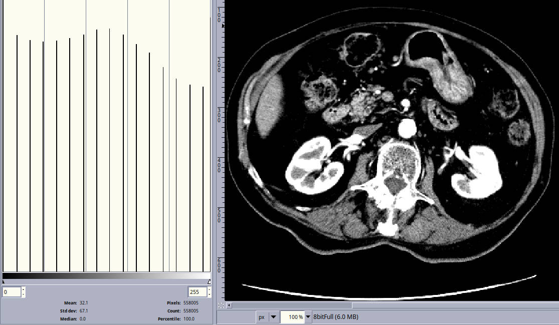
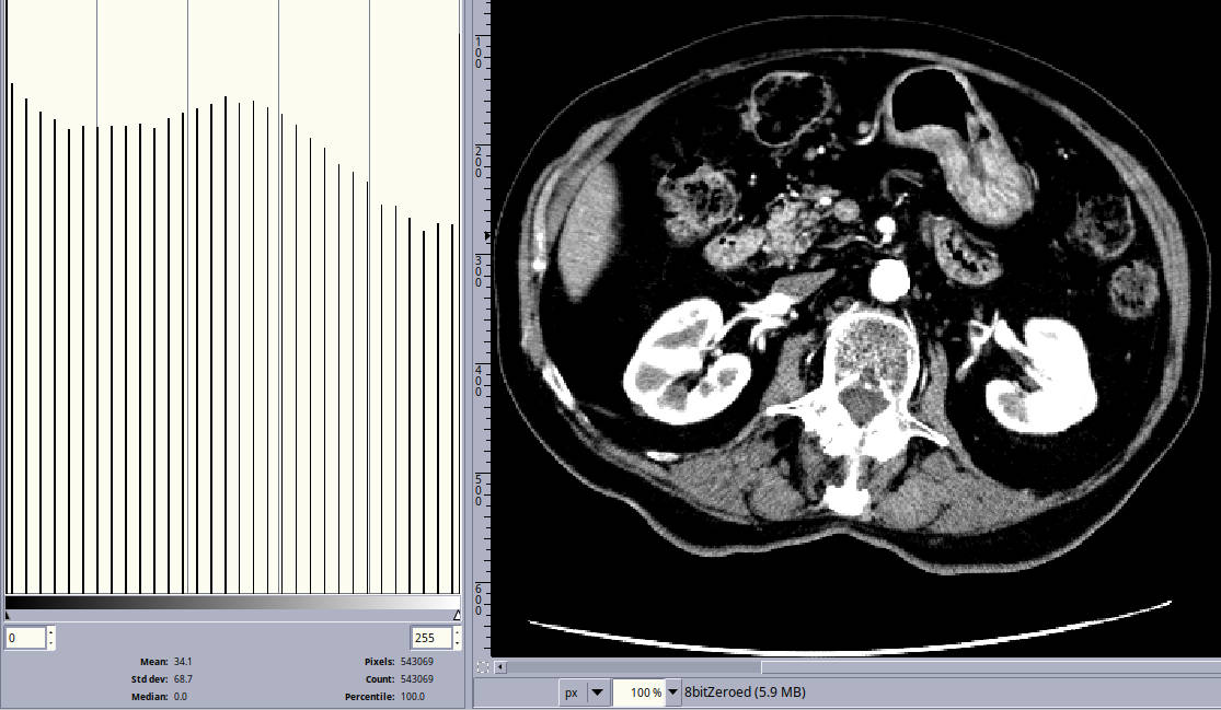
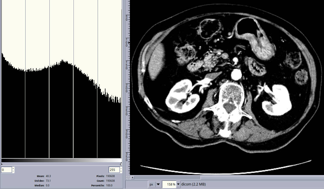
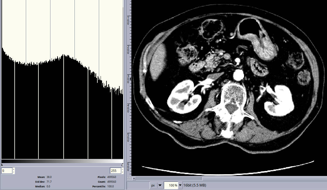
All of these images have the same abdomen window applied. Going Clockwise from top left:
Full4096 wide 8 bit png,
Zeroed2000 wide 8 bit png, Full 16 bit png, Original dicom rendered with Amide (So not displayed with this online ct viewer).
Notice the holes in the histogram in the bottom 2 images. We used a window that was 250 HU wide, so 5 values are missing (the left image has the missing values lining up really well with GIMP's unit markings).
A few things to note:
- The missing values in my 16 bit image aren't the same as the values in the real dicom viewer (and the
histograms are slightly different for what would be expected in a "lossless" conversion). There are many possible reasons for this:
- I apply a scaling factor to keep all my window values consistant, this possibly makes numbers round off slightly differently.
- The broswer's rendering method and Amide's are different, producing slightly different colors.
- Amide chooses to have their last hole at pure white, which means the intervals are evenly distributed from there, whereas my formulas center the holes evenly between each other and pure white and black.
- The images all look incredibly similar despite ranging from 17 to 251 values.
- I was surprised by this too, maybe marketing departments are lying to us when it comes to needing higher color definition :)
- Really the biggest constraint when it comes to the narrowness of your window is how heavily you apply jpg's compression. This should definitly be varried according to what window widths you offer.
- Some of the images are slightly brighter even though the window is the same.
- This depends on the width of the holes in the histogram.
- If a hole is wide, there is a larger range a window's level can be moved without the window changing.
- This means a window can be at the edge of this
range
which will cause it to be brighter or darker.
- Generally, this will never be noticed because the brightness of images varies wildly.
- This depends on the width of the holes in the histogram.
If you take a closer look at any of these images, please be aware of the zoom level of the straight dicom image. It was rendered smaller, so I had to scale it up slightly to match the others in GIMP which gives it a hint of antialiasing.
Custom Shaders
This viewer uses shaders for windowing, it is therefore possible to create any sort of effects which can be written with WebGL's GLSL variant.Some CT viewers employ other color spectra, these can be added through the use of custom shaders. Hopefully a simple conversion formula can be found to turn the value level (which grayscale images use) into a specific color. If that fails, you can always plot the value to color manually to make your own formula.
This tutorial will first walk you through simple custom shader creation. It will then cover the plotting/conversion of grayscale to RGB in a
Hot Metalspectrum. Finally it will add the new color spectrum to the viewer.
First, make sure you have:
- A working build of the viewer
- A text editor you like, preferably with syntax highlighting for JavaScript, however only a little JavaScript will actually be used (The one used in the example)
- A viewer set up with the images you wish to use. This tutorial will cover the typical 8 bit zeroed, 8 bit full, and 16 bit type images.
For these code heavy tutorials, it is recommended to full screen the video and watch at 720p
Resources
A cleaned up form of the code for the hot metal shader can be found here.
Note:
- The code is in it's own file, not
custom.js
as shown in the video.